

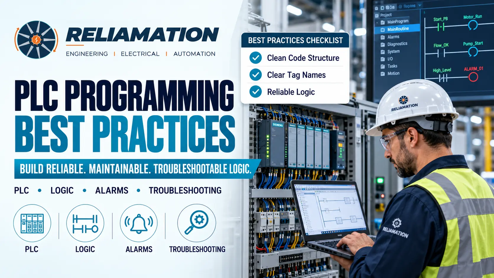
Programmable Logic Controllers are at the core of many industrial automation systems.
PLCs control machines, production lines, process equipment, motors, valves, conveyors, drives, and other industrial devices. However, a PLC program that simply works is not always a good PLC program.
Poorly structured logic can become difficult to troubleshoot, modify, or expand. Over time, this can increase maintenance effort, create unexpected production issues, and make future upgrades more difficult.
For this reason, following proven PLC programming best practices is important for building automation systems that are reliable, readable, and maintainable.
Reliamation provides PLC programming and integration services as part of its industrial automation and control-system engineering capabilities.
What Are PLC Programming Best Practices?
PLC programming best practices are design and coding methods that help engineers create control logic that is:
- Easy to understand
- Easy to troubleshoot
- Consistent
- Reliable
- Safe to modify
- Scalable
- Well documented
A good PLC program should make sense not only to the engineer who created it, but also to the technician or controls engineer who may need to troubleshoot it years later.
In addition, the program should reflect the actual machine or process clearly.
1. Use a Consistent Program Structure
One of the most important PLC programming best practices is using a clear and consistent structure.
Large PLC programs should not place all logic into one routine.
Instead, organize the program by:
- Machine section
- Process area
- Equipment type
- Control function
- Sequence
- Safety-related logic
- Alarm handling
- Communications
For example, a typical program structure may include:
- Main Program
- Conveyor Control
- Pump Control
- Valve Control
- Alarm Logic
- Communications
- Production Data
This structure makes it easier to locate the correct logic during troubleshooting.
In addition, engineers can work on one section without unnecessarily affecting unrelated logic.
2. Use Clear Tag Names
Tag naming is critical in industrial PLC programming.
Avoid vague names such as:
Motor1
Output12
Timer3
Instead, use descriptive names such as:
Conveyor01_RunCommand
Pump02_Faulted
Tank01_HighLevel
Line03_StartPermissive
A clear tag should explain what the signal represents.
For example, Pump01_RunFeedback is easier to understand than Input_145.
Descriptive tags reduce troubleshooting time and make PLC logic easier to review.
A consistent naming standard may include equipment name, equipment number, and function.
For example:
MTR_101_RunCmd
MTR_101_RunFb
MTR_101_Fault
MTR_101_AutoMode
The exact format can vary by plant. However, consistency is more important than the specific format.
3. Separate Commands, Status, and Feedback
Commands and feedback should not be treated as the same signal.
For example, a motor may have:
- Start command
- Run feedback
- Fault status
- Ready status
- Auto mode
- Manual mode
A start command only means the PLC requested the motor to run. It does not prove the motor actually started.
Therefore, good PLC programming should distinguish between command, device response, and verified status.
This improves troubleshooting and helps detect failed equipment.
4. Use Interlocks and Permissives Clearly
Industrial equipment often requires conditions to be true before it can operate.
These conditions may include:
- Safety system healthy
- Upstream equipment ready
- Downstream equipment available
- Correct valve position
- Pressure available
- Tank level acceptable
- No active fault
A good PLC program should make these permissives easy to identify.
For example, Pump_StartPermissive may be based on several conditions.
In addition, the HMI should clearly show which permissive is preventing equipment from starting.
This reduces operator confusion and troubleshooting time.
5. Avoid Excessively Complex Logic
Complex PLC logic is harder to maintain.
A single rung containing many nested branches, timers, comparisons, and conditions can become difficult to understand.
Instead:
- Break logic into smaller sections
- Use intermediate conditions
- Create reusable routines
- Use descriptive tags
- Add comments where necessary
For example, instead of repeating ten conditions everywhere, create a single LineReady condition.
As a result, the logic becomes easier to read and update.
6. Use Reusable Logic Where Appropriate
Many industrial systems contain repeated equipment.
Examples include:
- Pumps
- Motors
- Conveyors
- Valves
- Fans
- VFDs
Instead of creating completely different logic for every device, use standardized programming patterns.
On platforms such as Rockwell Automation Logix, reusable structures may include:
- Add-On Instructions
- User-defined data types
- Standard routines
Reusable logic helps create consistency across the project.
It can also reduce programming errors because tested logic is reused instead of recreated.
However, reusable code should remain understandable and documented.
7. Design for Troubleshooting
A good PLC program should help maintenance teams identify problems quickly.
Useful diagnostic information may include:
- Active fault
- First-out fault
- Failed permissive
- Communication fault
- Timeout condition
- Device not ready
- Sequence step
For example, an HMI should not simply display:
Machine Fault
A better message is:
Conveyor 2 Failed to Start – No Run Feedback
This gives the operator or technician useful information immediately.
Therefore, diagnostic logic should be considered during programming rather than added after commissioning.
8. Use Timers Carefully
Timers are common in PLC programming.
However, unnecessary or poorly documented timers can create difficult troubleshooting problems.
For each timer, engineers should understand:
- Why the timer exists
- What starts it
- What resets it
- What happens when it completes
For example, a motor start timeout may detect whether run feedback appears within five seconds.
If feedback does not appear, the PLC may generate a fault.
This is much better than using unexplained delays throughout the program.
9. Avoid Unnecessary Latches
Latch and unlatch instructions can be useful.
However, excessive use can make logic difficult to follow because the condition that turns a bit on may be far away from the condition that turns it off.
Where possible, use logic whose state can be clearly understood from current conditions.
If latches are required, document them carefully.
In addition, ensure the reset condition is easy to identify.
10. Use State-Based Sequence Control
Machines often operate through sequences.
For example:
- Idle
- Ready
- Starting
- Running
- Stopping
- Faulted
A structured state-based sequence can be easier to troubleshoot than many overlapping bits.
Each state should define:
- Entry conditions
- Actions
- Exit conditions
- Fault conditions
For example:
Step 20 – Start Conveyor
Action: Energize conveyor command.
Exit condition: Run feedback received.
Fault condition: No feedback within five seconds.
This approach makes sequence behavior clear.
11. Handle Alarms Properly
Alarm logic should provide meaningful information.
Each important alarm should define:
- Trigger condition
- Delay
- Priority
- Message
- Reset condition
- Operator response
Avoid generating unnecessary alarms.
Too many nuisance alarms can make operators ignore important warnings.
In addition, alarm messages should describe the actual problem.
Poor:
Fault 104
Better:
Pump 3 Overload Tripped
Clear alarms improve operator response and maintenance efficiency.
12. Add Useful Comments
PLC programs should include enough comments to explain logic that is not immediately obvious.
Useful comments may explain:
- Why a condition exists
- Special sequence behavior
- Legacy equipment limitations
- Communication logic
- Complex calculations
However, comments should not simply repeat the instruction.
Poor comment:
Starts motor
Better comment:
Starts exhaust fan after damper-open feedback is confirmed.
Good comments provide context.
13. Keep Safety Logic Separate
Safety-related logic should be clearly separated from normal machine control.
Safety systems may involve:
- Emergency stops
- Guard switches
- Light curtains
- Safety relays
- Safety PLCs
- Safe torque off
Safety logic should follow the required safety standards and approved engineering design.
In addition, normal PLC logic should not bypass or defeat safety functions.
This separation improves clarity and helps engineers understand the role of each system.
14. Test Logic Before Commissioning
PLC logic should be tested before plant start-up whenever possible.
Testing may include:
- Simulation
- Controlled input testing
- Sequence testing
- Alarm testing
- Interlock testing
- Failure scenarios
- Communication testing
For example, engineers should test what happens if:
- A sensor fails
- A motor does not start
- A valve does not reach position
- Communication is lost
- A permissive disappears during operation
Testing abnormal conditions is just as important as testing normal operation.
15. Maintain Version Control
PLC files should follow a clear revision process.
Avoid files such as:
Final.acd
Final_New.acd
Final_New2.acd
Instead, use a clear format such as:
Line1_MainPLC_Rev05_2026-09-28.acd
The revision history should record:
- Date
- Engineer
- Change made
- Reason
- Approval
In addition, create a backup after every approved change.
Version control becomes extremely important when multiple engineers work on the same system.
16. Keep Documentation Current
PLC logic should match project documentation.
Important documents may include:
- I/O list
- Electrical drawings
- Control narrative
- Network diagram
- Alarm list
- Sequence description
- Backup records
If a PLC change is made but documentation is not updated, future troubleshooting becomes harder.
Therefore, documentation should be treated as part of the control-system lifecycle.
17. Consider Future Expansion
A PLC program should not be designed only for today’s equipment.
Where practical, consider:
- Additional I/O
- Future machines
- New production lines
- SCADA integration
- Data collection
- Network expansion
For example, a reusable motor structure makes it easier to add another motor later.
However, avoid unnecessary complexity for features that may never be used.
Good PLC design balances flexibility with simplicity.
PLC Programming Best Practices Checklist
Use this checklist during PLC development and review.
Program Structure
- Logic divided into clear programs or routines
- Equipment logic organized consistently
- Sequence logic separated
- Communication logic separated
Tags
- Descriptive tag names used
- Naming standard followed
- Commands and feedback separated
- No unnecessary generic tags
Control Logic
- Permissives clearly defined
- Interlocks clearly defined
- Timers documented
- Latches minimized
- Fault handling included
Diagnostics
- Fault messages are descriptive
- Failed permissives are visible
- Communication failures are detected
- Sequence status is available
Testing
- Normal sequences tested
- Fault scenarios tested
- Alarm logic tested
- Interlocks tested
- Communication tested
Documentation
- Comments added where required
- Revision history updated
- PLC backup created
- Drawings updated
- I/O list current
Common PLC Programming Mistakes
Poor Tag Naming
Generic tags make troubleshooting slower.
Use descriptive names that clearly identify equipment and function.
Repeating the Same Logic
Duplicated logic increases the chance of inconsistent changes.
Use standardized routines where appropriate.
Overly Complex Rungs
Long and deeply nested logic is difficult to troubleshoot.
Break complex logic into understandable conditions.
Missing Fault Diagnostics
A machine may stop without telling the operator why.
Build useful fault information into the program.
No Version Control
Without revision control, engineers may load the wrong PLC program.
Use consistent file naming and backup procedures.
Testing Only Normal Operation
A system may work perfectly when everything is healthy but fail during abnormal conditions.
Always test failures and unexpected conditions.
Why Good PLC Programming Matters
Following PLC programming best practices can help industrial facilities:
- Reduce troubleshooting time
- Improve system reliability
- Simplify maintenance
- Reduce programming errors
- Improve operator diagnostics
- Support future expansion
- Improve documentation
- Make upgrades easier
More importantly, well-structured PLC logic makes the control system easier to understand throughout its lifecycle.
How Reliamation Supports PLC Programming
Reliamation develops and implements PLC software as part of its industrial automation services.
Its PLC programming capabilities include logic design, coding, testing, and integration for industrial applications.
The company also provides HMI, DCS, and RTU software development as part of broader control-system solutions.
Whether a facility needs a new PLC application, an existing-program modification, troubleshooting support, or integration with SCADA and other systems, structured programming practices can improve reliability and long-term maintainability.
Need PLC Programming Support?
Contact Reliamation to discuss PLC programming, control-system integration, troubleshooting, and industrial automation requirements.
Frequently Asked Questions
What are PLC programming best practices?
PLC programming best practices are methods used to create control logic that is clear, reliable, maintainable, and easy to troubleshoot. They include consistent program structure, descriptive tags, diagnostics, documentation, and testing.
Why is PLC program structure important?
A clear structure helps engineers locate logic quickly, understand machine behavior, and make changes without affecting unrelated parts of the program.
What makes a good PLC tag name?
A good tag name clearly describes the equipment and signal function, such as Pump01_RunFeedback or Conveyor02_Faulted.
Should PLC programs use reusable logic?
Yes. Reusable logic can improve consistency and reduce programming effort when similar equipment is used repeatedly. However, reusable structures should remain well documented.
Why should PLC logic include diagnostics?
Diagnostics help operators and maintenance teams identify the reason for equipment failures instead of only showing that a fault occurred.
How often should PLC programs be backed up?
A new backup should be created after every approved programming or configuration change.
Should PLC logic be tested before commissioning?
Yes. Logic should be tested through simulation, FAT, or other controlled testing methods whenever practical before live plant commissioning.
What information should be included in PLC documentation?
Useful documentation includes I/O lists, control narratives, sequence descriptions, alarm lists, network diagrams, comments, and revision history.
Frequently Asked Questions
Get answers to common questions about industrial automation, PLC migration, HMI, SCADA, and control-system integration.
Reliamation provides industrial automation services including PLC programming, HMI and SCADA development, control system integration, legacy control-system migration, industrial networking, data reporting, system troubleshooting, and automation modernization.
Yes. Reliamation helps manufacturers migrate legacy platforms such as PLC-5 and SLC 500 to modern ControlLogix and CompactLogix systems while minimizing production disruption and preserving essential control functionality.
A PLC controls machines and industrial processes, an HMI allows operators to interact with equipment, and a SCADA system provides plant-wide monitoring, control, alarms, historical data, and reporting.
Yes. Reliamation develops custom HMI and SCADA solutions designed around each facility’s equipment, operating requirements, alarm strategy, security standards, and reporting needs.
In many cases, yes. A phased modernization approach can retain compatible equipment while replacing obsolete controllers, communication networks, operator interfaces, and other high-risk components.
Reliamation’s automation and control-system solutions can support manufacturing, food and beverage, plastics, packaging, material handling, water treatment, energy, and other process-driven industries.
Industrial automation can reduce downtime through reliable controls, real-time alarms, equipment diagnostics, historical data, preventive-maintenance insights, and faster troubleshooting.
You can contact Reliamation through the website to discuss your existing control system, operational challenges, modernization requirements, and project goals with an industrial automation specialist.